Why Swap?
- The original '77 280z's build has an
external mechanical voltage regulator that is unreliable and unstable with
age. It is actually based upon elements that open and close many times
each second due to heating and cooling. The principal is not much
different than the overheat protection devices commonly used in your
toaster and hairdryer. It also requires frequent adjustments of gaps much
like spark plugs.. The newer ZX alternator incorporates a built in
solid-state voltage regulator that requires no maintenance and is more
stable.
- The wiring between the alternator and
voltage regulator typically is problematic. On the ZX unit, the regulator
is inside the alternator body so there are no interconnections to worry
about.
- The Z alternator is rated at 50A. The ZX
alternator is rated at 60A (It is physically bigger)
- The upgrade is pretty much bolt and go. Two
wires need to be jumpered or spliced and that is it!
- The ZX unit is newer, readily available in
junk yards and inexpensive.
- The ZX unit is rock solid an the DC voltage
is 14.45V at all RPMS (as measured on mine).
- No more wavering Voltage gauge or hunting of
the fuel pump.
- This swap worked great in my 77 280z. I
assume it will work in 75 & 76 280Z's. I do not know about 240 or 260
Z's.
Compatible Donor Alternators:
- All 280ZX units. Turbos are 70Amp and N/A
are 60Amp. '78 Z units also work and are 60Aamp.
- Other Nissan units should work but
size or wiring or pulleys may require mods to work (double check your
potential source against pics of the stock unit below)
Big Thanks to Z-Creations for info on how to do
this swap! Click
Here.
Physical Comparison:
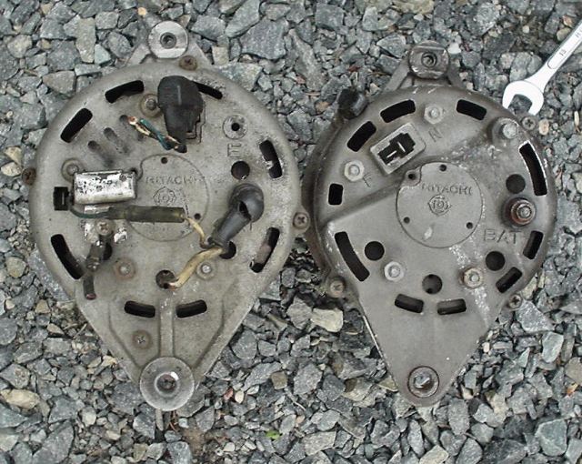
ZX alternator on left, Z alternator on right.
Note that all three needed connectors are the same:
- E (Black Wire and Condenser) This
connection is Earth or Ground
- BAT (White wire with Red Stripe and other end of condenser
wire) This connection is +12V output
- F&N (T connector)
N (Yellow) (on the early alt becomes the Sense signal on the newer alternator (the
alternator "senses" the voltage on this wire and attempts to
maintain it at 14.45V.
F (white with black stripe) is the Field signal on the early alt that becomes the L lamp signal
on the newer alternator.
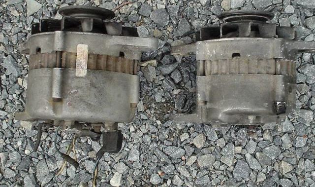
From the top. The ZX on the left is clearly bigger. It is rated at 60A
compared to the Z's 50A
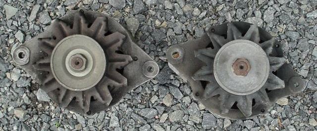
Pulleys seemed to be the same but ZX fan on left is bigger
Ths Swap:
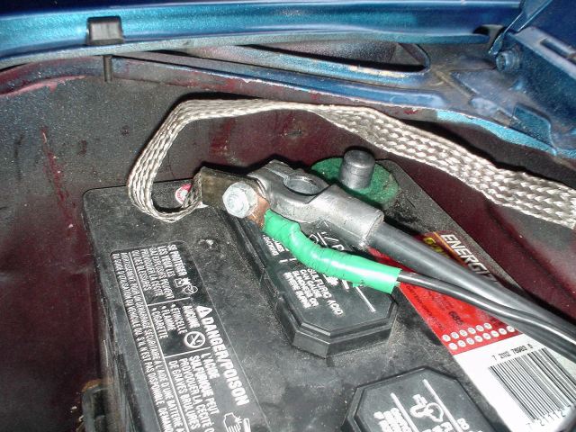
Disconnect - Neg battery terminal (note I repositioned my battery so that the
- neg side is near the firewall).
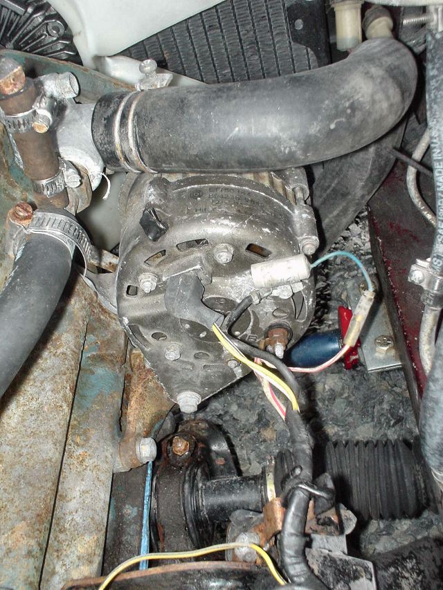
Here is a pic of the stock 77 alternator before doing anything (use as a
reference if needed)

Here is a another reference pic

FYI Name plate on stock 77 alternator "12V @ 50A"
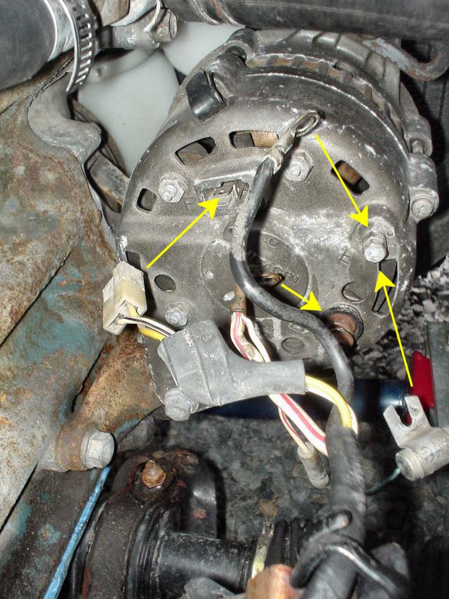
Disconnect the cables to the alternator

Remove 3 bolts that hold alternator in place. I used a 13mm socket for the top
bolt that clamps it to the bracket and a 12mm socket for the two bolts holding
it to the engine block.
Here is a pic of an easy way to access the lower front bolt. The rest of the
work can be done from the top.
Unclamping the carbon canister and moving it aside takes 30sec to do and helps
a lot.
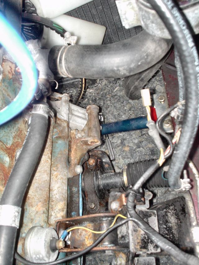
Alternator removed
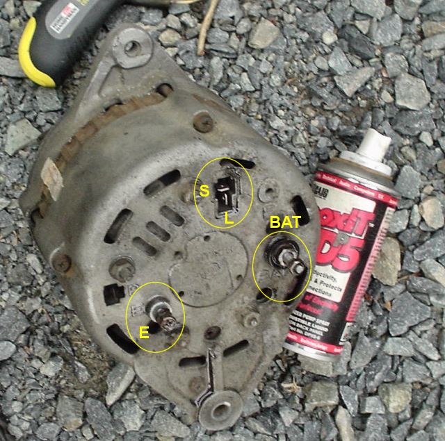
Freshen contacts/connectors on new alternator with sandpaper or scotch pad and
contact cleaner (Caig Deoxit above)
You just need to do the BAT, E and "T" contacts. Also do the same
with the cable ends in the car.
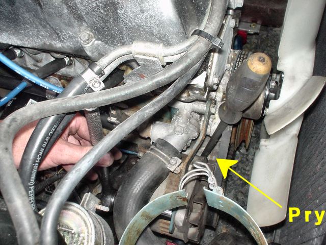
Install new alternator:
- Bolt it in place with 3 bolts but only turn
them to "finger tight"
- Install the fan belt
- Use a long screwdriver or broom handle or
similar to pry the alternator away from the engine as shown above. Tighten
the top bolt with a ratchet while the fan belt is in tension.
- Check tension by pressing firmly on fan
belt. ~ 1/2" deflection is fine.
- Tighten all 3 bolts
- Re-connect wires

Locate Voltage Regulator. It is under the bracket holding the fusible links. A
10mm socket removed the 4 bolts.
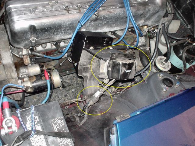
Here is the bracket removed. You can see the Voltage Regulator and it's inline
connector
Here is a schematic of the ZX alternator. Note the
internal voltage regulator.
- BAT (+12V battery) connection (White with
red striped)
- E (earth/ground) connection (Black) are the
same on both alternators and require no changes.
- S (Sense) connection (Yellow) gets connected
to a +12V source
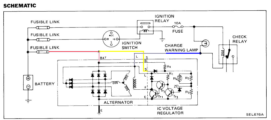
- L (Lamp) connection (White with black
stripe) gets connected to a +12source that is active only when the car is
cranked by the starter. (You can see the node in the schematic where the L
lines get power from the warning lamp when cranking and then from the
alternator windings via the 3 clustered diodes when operating)
Electrical Jumpers
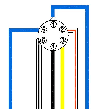
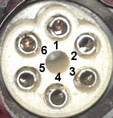
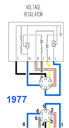
This is the wiring to the electrical harness connector (as seen on the car
when you unplug, remove, smash into bits, tramp on and throw away the
external voltage regulator)
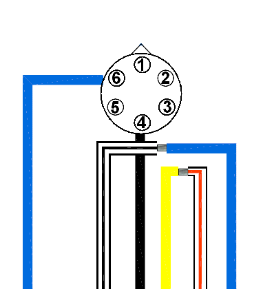
Here are the two connections to make: 2 to 3 and 1
to 5.

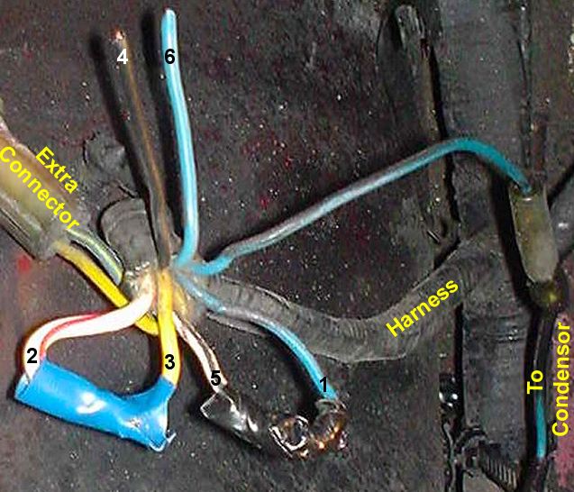
Connect, solder, heat shrink, insulate and wrap
Double check everything (wires correct and
snug, bolts tight, fan belt snug and on correct pulleys, no tools in engine
compartment, carbon canister put back and hose put on, correct jumpers at
connector)
Connect -neg battery cable briefly (1sec) and make sure there are no sparks or
smoke!
If all seems ok, connect -neg battery cable and try starting. Watch for smoke
and watch the battery gauge for correct voltage and Red LED functioning.
Enjoy!
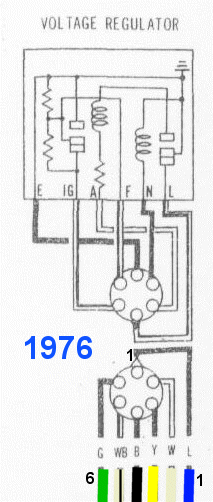
FYI if you have a '76 280z, the colours are
slightly different:
- The white with red striped wire on the
77 is just white on the 76 (still pin 2)
- The blue wire on the 77 is green on the 76
(still pin 6 and unused)

Here are the '76 connections for your convenience
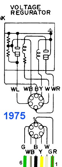
Ok, many people are still confused. Here are
the jumper connection details for each year
| |
 |
 |
 |
| |
1975 |
1976 |
1977 |
Connect 1-5
(lamp to windings common) |
green&red to
white&black |
blue to
white&black |
blue to
white&black |
Connect 2-3
(+12V to Sense) |
white to yellow |
white to yellow |
white&red to
yellow |
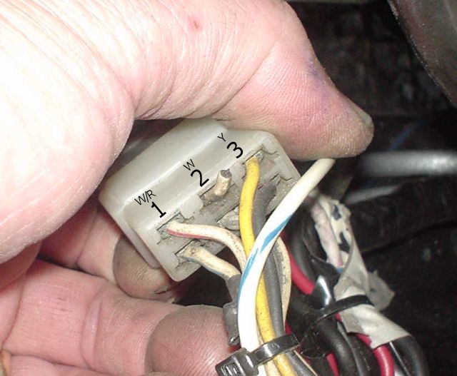
'73 240z Connector to VReg (Rectangular)
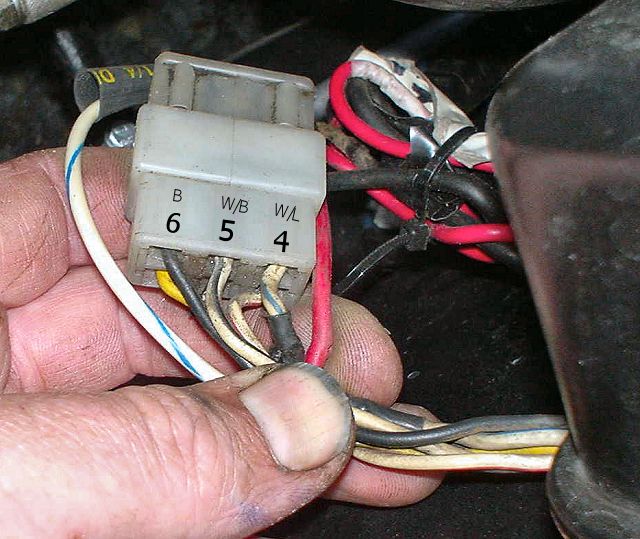
Great post on www.Zcar.com
Author: xtinc
Date: May 14, 10:48am
I followed these instructions I found on the net and it worked perfect. Also
before you do this, do a search on this site for diode. Sometimes when you
convert to an internal regulator, the car will not shutoff when you turn the
key to off, this is due to current bleeding through the alternator, a diode
must be placed in the circuit to block it
Good luck
Converting to an internal regulator alternator
Question:
I
would like to know if anyone has converted from the external regulated
alternator to an internal. What wiring did you change?
Answer:
First a
little background: The 60 amp internal regulator alternator was used on the
'78 280Z and then the non-turbo 280ZX. I have also seen it on the '78-'85 810/Maxima
and the '81-'85 720 pickup trucks. It is marked "LR160" on the case.
There was also a 70 amp version (marked LR170) that was used on the 280ZX
turbo's.
[Note: It looks like the '84-'86 non-turbo 300ZX 70 amp alternator could be
used as well, but the wiring connectors are different, so get (i.e., cut it
off) the corresponding engine harness connectors as well if you get one of
these alternators. I'll write this up this conversion later.]
Because I don't like to give instructions without some explanation of what you
are doing (it makes troubleshooting easier), I will start by describing the
internally regulated alternator's electrical connections:
1. An
"L" connection which goes to a "switched" 12V supply. By
this I mean a 12V source that is active only when the ignition switch is in
the ON position. I use the mnemonic "L" for "lamp", the
alternator warning lamp (if used) is in series with this connection. This
terminal also supplies the "excitation" current to the alternator
field winding at engine turn on, allowing the alternator to begin producing
voltage as the engine is ramping up to idle speed. Once the alternator rotor
is turning fast enough, it generates it's own supply for the field winding and
the current in the "L" connection stops flowing. The warning lamp
(if used) goes out.
2. An
"S" connection which goes as close to the positive terminal of the
battery as physically possible. The "S" connection
"senses" the battery voltage and this is the voltage that the
regulator is tying to control. This connection has a high impedance, so it
only draws only micro amps from the battery, so it can be left connected
without fear of battery discharging.
The "L" and "S" connections are in the plug connector on
the rear
of the alternator that looks like the capital letter "T". The top
of the "T" is the "S", and the other part of the
"T" is the "L". Or
in crude ASCII art:
............
: ------- : "S"
:.... | ....:
: | :
: | : "L"
:...:
3. An
"A" terminal, which is the output of the alternator, which also is
connected to the positive terminal of the battery. This connector carries the
charging current. Because of the high currents this wire must carry, it is a
low gauge wire, which means it has a large cross sectional area. For safety
reasons, a fusible link should be in series with this connector. The
"A" terminal is the insulated threaded stud on the rear of the
alternator.
Of course, someone may ask: "Why do you need two separate (the
"S" and the "A") connections between the battery and
alternator?". It is because of the fact that even large wires have some
resistance, and therefore there will be a voltage drop between the alternator
and the battery when the battery is being charged. If the regulator sensed the
alternator output (which is higher in voltage) and not the battery terminal,
the result would be undercharging of the battery. Now there are alternators
which work this way, but they need a fairly large diameter charging wire to
reduce the voltage drop. The separate "S" connection is a much
better method of regulation.
4. There
is a "P" terminal on the 280ZX turbo alternator (but I have also
seen it on a few of the non-turbo 280ZX alternators). There is not a
corresponding connector on the engine harness to mate with the "P"
terminal, even on the turbo 280ZX's. So, the "P" terminal is not
used/needed.
5.
Finally, there is a ground connection on the alternator, although the case is
a pretty good ground connection to the engine block.
Now, the following procedure only applies to the 240Z. The 260Z has electrical
connections between the regulator and the interlock module and the electric
fuel pump, so it's more difficult to convert to an internally regulated
alternator, but I have a procedure for it as well. Please email me directly if
anyone is interested. I have not looked into converting a 280Z, but I would
think that it would be possible as well.
1.
Disconnect the battery.
2. Unplug
the external regulator and note the color code of the wires that are on the
regulator connector of the engine wiring harness. You will be connecting some
of these wires together, so get another plug from a junked regulator or cut
the one off your old regulator. Now the wire colors I will be referring to are
on the regulator connector of the engine wiring harness. This is because
although the regulator wire colors match the engine harness with the stock
regulator, I've noticed that some aftermarket regulators have a different wire
color code.
3.
Connect the white wire to the yellow wire. This connects the battery to the
"S" input.
4.
Connect the black with a white stripe wire to the white with black stripe
wire. This connects the "L" terminal to a switched 12V.
5.
Disconnect and unbolt your old alternator. Bolt up the new alternator.
Depending on what particular internally regulated alternator you use (I've
seen different pulley sizes), you might need a different length belt.
6. At the
alternator, connect the white with red stripe wire of the engine wiring
harness to the threaded stud (the "A" terminal) on the alternator.
This connection provides the charging current for the battery. Connect the
black ground wire to the alternator. Don't forget to include any bypass, or
filter capacitor. Plug the two-pin "T" connector into the
alternator.
7.
Re-connect the battery and start the engine. With a good digital voltmeter
measure the voltage directly across the battery terminals. This is the
charging voltage. It should be 14.7V +/- 0.3V, but this voltage is a function
of the ambient temperature and the state of charge of the battery. If the
voltage reading is not correct, then re-check your wiring. More than 15.0V
indicates that the "S" connection may not be connected correctly.
Author: Pellius
Date: Jul 5, 7:08pm
BTW, with regard to the terminal
marks on the GM alternator case:
GM/Delco "1" = GM/Delco "R" = Datsun "L" = warning lamp/Switched +12v
GM/Delco "2" = GM/Delco "F" = Datsun "S" = constant +12v current sensor


