Details on how to upgrade AFM housing from smaller stock size to a larger size.
Be sure to verify A/F ratios using a
wide band Oxygen Sensor to ensure the new AFM is set up correctly.
Pros:
- Easy to do.
Cons:
- Need to make new mounting bracket
- Relative increase in size is only 34%
Comparison Via Photos (Larger AFM is from a Toyota Cressida) :
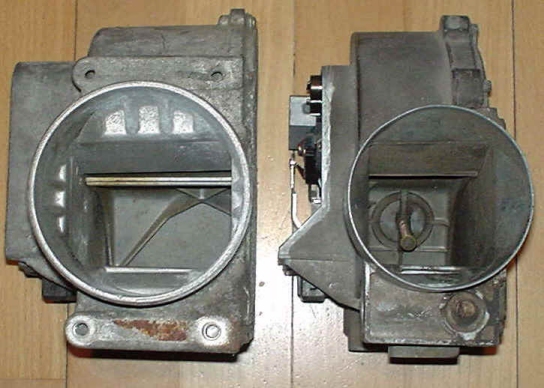
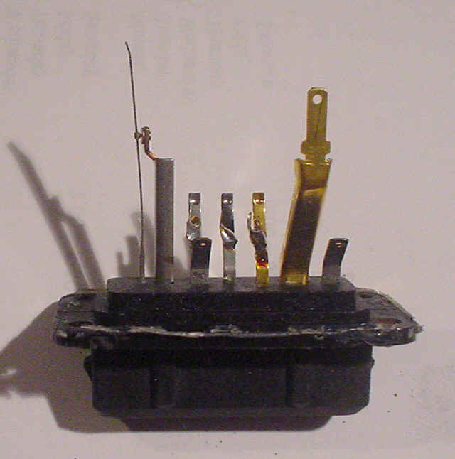
Outlet side (note it is the rectangular cross
section inside that restricts the flow) stock AFM on right
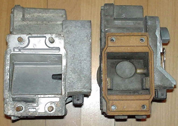
Intake side ( the restrictive rectangular cross
section is easy to see. Also shown is the temperature sensor)
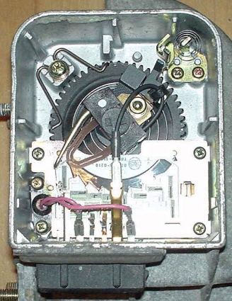
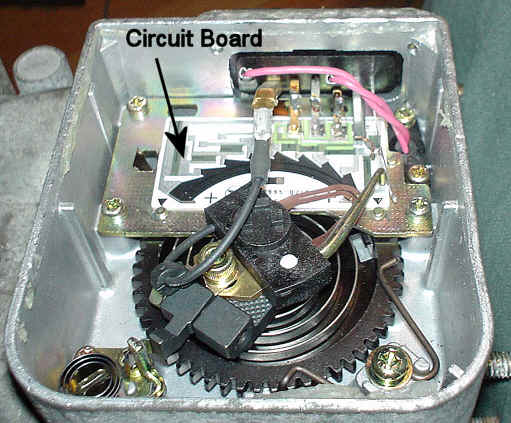
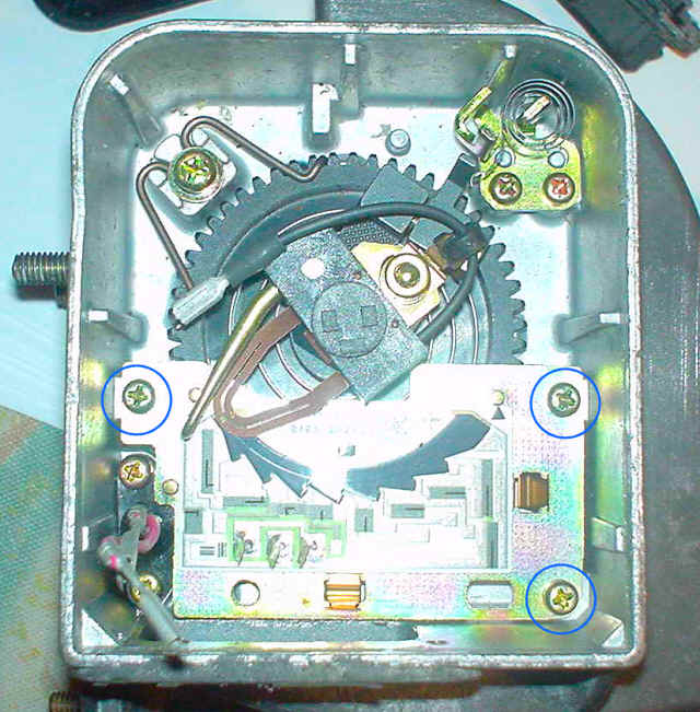
AFM electronics compartment detail (note the
circuit board held in place with 3 screws)
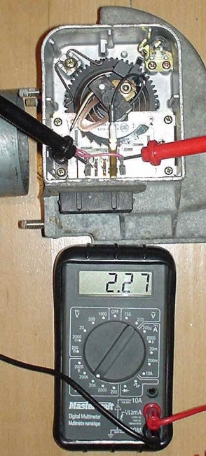
Measuring the temp sensor's resistance (~2270ohms
at room temp ~ 21°C)
Flow Restriction Comparison and Temp Sensor Comparison:
| Parameter | Stock 280z AFM | Cressida AFM |
| outlet flange diameter (ID) | 67mm | 74mm |
| outlet flange cross sectional area | 3526mm sq | 4300mm sq |
| intake flange dimensions | 50mm X 46mm | 63mm X 49mm |
| intake flange cross sectional area | 2300mm sq | 3087mm sq |
| Relative size (restrictions) | X1 | X1.34 |
| Temp Sensor Resistance @ 21°C | 2,270ohms | 2,280ohms |
How to swap:
The only part that has to be moved is the small circuit board. It moves from the stock AFM to the larger turbo AFM. (Assuming temp sensors are the same)
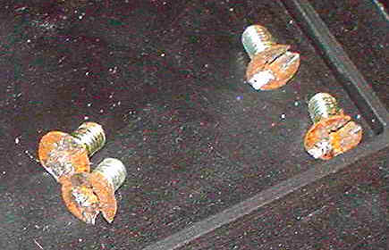
- Remove the connector (4 screws and silicon)

I had to "dremel" slots in the rusty screws to remove them.
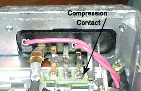
- The contacts from the connector to the circuit
board are actually compression fit so the connector simply pulls out with
the contacts
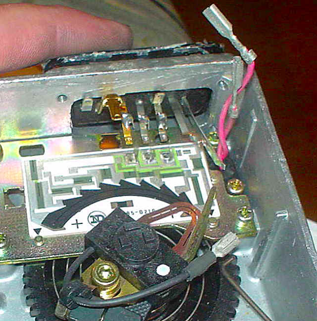
Disconnect the two wires from the temperature sensor (red) and the wire from the wiper (black).
Disconnected connector being removed.
Disconnected Connector
It is easy to see the two connectors are not 100% swappable

- Remove the three screws holding the circuit
board in place.
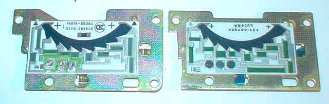
Circuit Boards Removed (Note the clipping needed for the Nissan unit to fit the Cressida AFM)
- Swap circuit boards and reassemble.

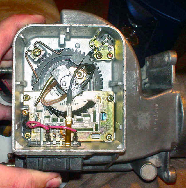
Nissan circuit board in Cressida AFM
Finished!
- Since the flow resistance decreases as the
cross sectional areas increase, spring tensions on the turbo AFM will not
match those on the stock AFM. The AFM calibration process here
will not properly set the correct Turbo AFM's spring tension. It
should, however, get you close. You can then tweak a few teeth at a time to
optimize.
More AFM info here.
- For your reference, here is some data I
collected from my stock '77 280z AFM with outside temp=6°C:
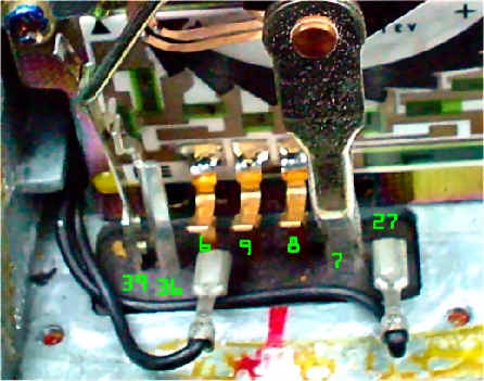
AFM Measurements taken on a 77 280z referenced to chassis ground.test
point39 36 6 9 8 7 27 Vreg temp rpm 800 13.93 13.93 0.01 11.59 7.48 3.22 5.09 14.04 6 1000 13.92 13.92 0.01 11.64 7.52 4.14 5.14 14.08 6 1200 13.98 13.98 0.01 11.7 7.56 4.68 5.23 14.15 6 1400 14.03 14.03 0.01 11.76 7.59 4.99 5.21 14.18 6 1600 14.35 14.35 0.01 12.06 7.78 5.41 5.25 14.49 6 2300 14.32 14.32 0.01 12.05 7.75 5.82 5.25 14.45 6
Normalized data (to 12V standard) from above table
test point
39
36
6
9
8
7
27
Vreg
temp
rpm
800
11.91
11.91
0.01
9.91
6.39
2.75
4.35
12.00
6
1000
11.86
11.86
0.01
9.92
6.41
3.53
4.38
12.00
6
1200
11.86
11.86
0.01
9.92
6.41
3.97
4.44
12.00
6
1400
11.87
11.87
0.01
9.95
6.42
4.22
4.41
12.00
6
1600
11.88
11.88
0.01
9.99
6.44
4.48
4.35
12.00
6
2300
11.89
11.89
0.01
10.01
6.44
4.83
4.36
12.00
6
The ECU sends a voltage ratio to the ECU. The ratio is U/Ub as per the schematic below.
V Ref Resistance (9-8) Vu (8-7) Vub (9-6) Vu/Vub 3.51 3.64 9.90 0.37 3.51 2.88 9.91 0.29 3.51 2.44 9.91 0.25 3.53 2.20 9.94 0.22 3.54 1.96 9.98 0.20 3.57 1.60 10.00 0.16 The following model shows Vu/Vub vs RPM
Harris Model: y=1/(a+bx^c)
Coefficient Data:
a = -62.727835
b = 46.860151
c = 0.049964787
Applying the model to other rpms yields (normalized and assuming Vub=10 and Vpin9=10):
RPM Vu/Vub 7 3000 0.139 5.048 4000 0.122 5.220 5000 0.111 5.328 6000 0.104 5.403 7000 0.098 5.460
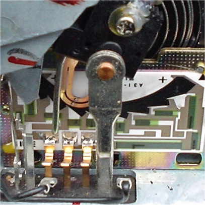
AFM wiper at 1500rpm

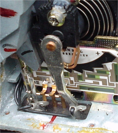
AFM wiper at 3000rpm
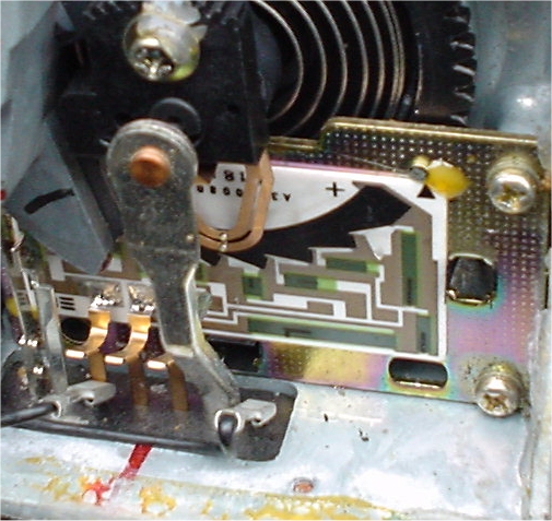
AFM wiper at 4000rpm
AFM Schematic
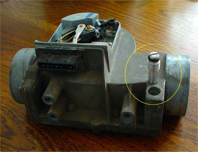
Here you can see the AFM bypass adjustment screw.
It is used to close a passage under the primary AFM passage.
This passage is primarily used to vary the air to fuel ratio at idle. The
screw controls how much "extra air" bypasses the AFM.
Closing passage is accomplished by turning the screw CW.
btw When the intake "pops" aka front fire usually due to running
lean;. the energy passes through this passage.
If it is closed off, the energy will damage the flap.